本文包含原理图、PCB、源代码、封装库、中英文PDF等资源
您需要 登录 才可以下载或查看,没有账号?注册会员
×
廉价的复合信号处理器消除了外部模拟电路。
将一个LVDT(线性可变差分变压器)连接到微控制器是有挑战性的工作,因为LVDT需要交流输入激励和交流输出的测量,以确定其可移动核的位置(参考文献1)。多数微控制器都缺乏专用交流信号生成与处理能力,因此需要外部电路产生任意谐波、波幅与稳定频率的正弦波信号。LVDT输出信号的波幅与相位转换成与微控制器内部ADC兼容的形式,一般需要添加外部电路。
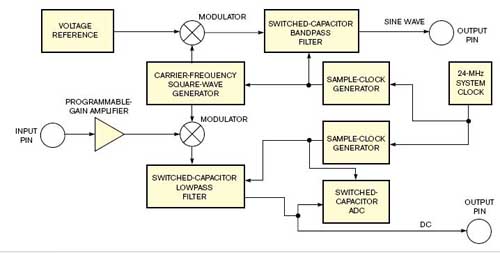
与传统微控制器相比,Cypress半导体公司的PSoC微控制器含有用户可配置的逻辑和模拟模块,简化交流信号的生成与测量。PSoC器件具有无需连续CPU的干预就能生成模拟信号的独特功能。PSoC灵活的模拟与数字模块可以驱动一支LVDT,并无需外部电路就可以测量其输出。图1显示的是LVDT接口的完整电路,图2显示的是PSoC微控制器的内部电路框图。
图1 LVDT接口的完整电路

图2 PSoC微控制器的内部电路框图
PSoC采用多对用户可配置的开关电容器模块,实现带通和低通滤波器。通过生成方波,并通过建立在首个开关电容器模块中的稳压器,加在PSoC开关电容滤波器上,从而创建高质量正弦波。通过一个中心位于方波基频的窄带带通滤波器,方波可以去除绝大多数谐波。
为从PSoC开关电容带通滤波器产生最高保真度的正弦波,要使用尽可能高的过采样速率,因数约为33,即每个正弦波周期33阶。合成的正弦波足够平滑到足以驱动能衰减残余更高谐波的LVDT。用可编程增益放大器调整PSoC的内部电压基准,可以在滤波前对方波幅度作粗略的控制。为补偿波形直流偏置电压,放大器对2.6V内部模拟地基准进行缓冲,并驱动用作LVDT模拟地回路的输出管脚。
LVDT输出由幅度可变的正弦波电压组成,其相对于正弦波激励电压的相位角要经受一个相当大的可变移位,有时相移会超过180。LVDT的信号驱动PSoC的可编程增益放大器,其输出送至开关电容低通滤波器,跟随一个用于同步整流的稳压器。整流后的信号驱动一输出管脚,以及PSoC的开关电容ADC。
将LVDT输出加在同步稳压器上,跟随一个低通滤波器,产生直流电压送至ADC或直接驱动模拟反馈控制系统。在PSoC微控制器中,连接到ADC的低通开关电容滤波器需要相同的采样时钟驱动这两个电路,导致PsoC的11位Δ-S ADC的转换速率大约是低通滤波器角频率的一半。同步稳压产生两倍激励频率纹波频率,因此更容易被低通滤波器去除。将、重新设计低通滤波器的角频率为激励频率的三分之一,就可以在等于或低于1 LSB(最低有效位)标准差下,使LVDT输出的测量达到11位分辨率。
用配置为计数器链的逻辑电路块将PsoC的24MHz内部系统时钟分频,产生开关电容器模拟电路模块所需的数字时钟信号。在加电或复位后,PSoC的CPU配置所有可配置的模拟和数字电路模块,并开始运行。从那以后,硬件便能够激励LVDT,并无需CPU参与的情况下,以每秒500次采样速率测量其输出。当PSoC CPU运行在12MHz时,处理ADC内部动作和中断只消耗CPU不到3%的资源。
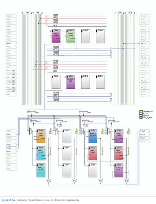
大量PSoC资源仍可用于计算LVDT位置,以及在LCD模块上以文本形式显示结果。四个模拟电路模块、五个逻辑电路模块和很多I/O管脚都可用于支持更高要求的应用。图3显示了可用于附加功能的可配置模块。

图3 可用于附加功能的可配置模块
参考文献:
1、"Linear variable differential transformer," Wikipedia
英文原文:
PSoC microcontroller and LVDT measure position
Low-cost mixed-signal processor eliminates external analog circuitry.
Sigurd Peterson, Sig3 Consulting, Aloha, OR; Edited by Brad Thompson and Fran Granville -- EDN, 10/26/2006
Connecting an LVDT (linear-variable-differential transformer) to a microcontroller can prove challenging because an LVDT requires ac-input excitation and measurement of ac outputs to determine its movable core's position (Reference 1). Most microcontrollers lack dedicated ac-signal-generation and -processing capabilities and thus require external circuitry to generate hARMonic-free, amplitude- and frequency-stable sine-wave signals. Conversion of an LVDT's output signals' amplitude and phase into a form compatible with a microcontroller's internal ADC usually requires additional external circuitry.
In contrast with conventional microcontrollers, Cypress Semiconductor Corp's PSoC microcontrollers include user-configurable logic and analog blocks that simplify generation and measurement of ac signals. PSoC devices have the unusual feature of being able to generate analog signals without demanding continuous CPU attention. The PSoC's flexible analog and digital blocks can drive an LVDT and measure its outputs without requiring any external circuitry. Figure 1 shows the complete circuit of the LVDT interface, and Figure 2 shows the PSoC microcontroller's internal circuit blocks.
The PSoC uses pairs of user-configurable switched-capacitor blocks to implement both bandpass and lowpass filters. You can create a high-quality sine wave by generating a square wave and applying it to a PSoC switched-capacitor filter through a modulator built into the first switched-capacitor block. Passing the square wave through a narrow bandpass filter centered on the square wave's fundamental frequency removes most of the harmonics.
To obtain the highest fidelity sine waveform from a PSoC switched-capacitor bandpass filter, use the highest possible oversampling rate |
 |手机版|MCU资讯论坛
( 京ICP备18035221号-2 )|网站地图