本文包含原理图、PCB、源代码、封装库、中英文PDF等资源
您需要 登录 才可以下载或查看,没有账号?注册会员
×
Driving Strain-Gauge Bridge Sensors with Signal-Conditioning s
Abstract: Strain-gauge sensors - reliable, repeatable, and precise - are used extensively in manufacturing, process control, and the research industries. They transduce (convert) strain into an electrical signal for use in pressure sensors, weight measurements, force and torque measurements, and materials analysis. A strain gauge is simply a resistor, whose value varies with strain in the material to which it is bonded. The article covers the MAX1452 sensor signal conditioner for temperature compensation. The MAX1452's flexible approach to bridge excitation gives the user a substantial amount of design freedom. This article has focused src="/data/attachment/portal/201007/ET33818201007230417401.gif">
Figure 1. Strain gauges wired in a Wheatstone bridge configuration.
In a half-active Wheatstone bridge circuit (Figure 2), src="/data/attachment/portal/201007/ET33818201007230417402.gif">
Figure 2. Strain gauges wired in a half-active Wheatstone bridge configuration.
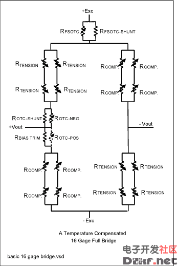
Another fully active bridge circuit (Figure 3) employs more than four active 350Ω strain gauges. The characteristic bridge resistance is 350Ω and the output sensitivity is 2mV/V, but the material under strain is distributed over a wider area of the gauge.

Figure 3. A 16-gauge Wheatstone bridge configuration. Effects of Temperature src="/data/attachment/portal/201007/ET33818201007230417404.gif">
Figure 4. The MAX1452 is a highly integrated signal-conditioning IC for bridge sensors.
The MAX1452 includes PRT current-excitation circuitry (Figure 5). The circuit includes a current mirror (T1 and T2) that amplifies a small reference current by a factor of 14—to a level sufficient to drive a PRT sensor in the 2kΩ to 5kΩ range. The reference current is derived by imposing a voltage src="/data/attachment/portal/201007/ET33818201007230417405.gif">
Figure 5. Circuit diagram of bridge excitation for PRT.
The FSO DAC has a sigma-delta architecture, and derives its digital input from a temperature-indexed table of coefficients in flash memory. Each temperature increment of 1.5°C provides a unique 16-bit coefficient to the DAC every 4ms. The DAC's output voltage drives the gate of p-channel MOSFET T1, which in turn drives sufficient current into RISRC and RSTC to produce a voltage equivalent to the FSO DAC voltage. The current through T1, mirrored through T2 by a factor of 14, becomes the bridge-drive current.
Resistor RSTC enables first-order modulation of the sensor-excitation current as a function of temperature. For silicon PRT transducers, temperature is derived from the resulting sensor bridge voltage when a current is passed through the bridge. Such sensors feature a very good transfer function between the bridge resistance and temperature. By exciting the bridge with current, you can scale the resulting bridge voltage and use it for first-order compensation of offset and sensitivity. This is accomplished by routing the bridge voltage (pin BDR) to the reference input of the full-scale output temperature-compensation DAC (FSOTC DAC). Remember, however, that current excitation does not generally apply when foil or thick-film strain gauges are used. Voltage-Drive Circuits
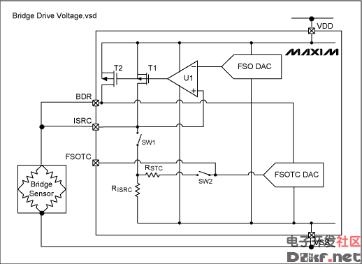
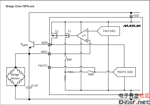
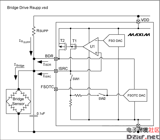
The MAX1452's internal 75kΩ resistors can serve for RISRC and RSTC, or external resistors can be routed by switches SW1 and SW2, as shown in Figure 5. The ISRC pin gives access to the op amp and allows voltage feedback from the bridge drive. Figures 6, 7, and 8 depict three different voltage-drive circuits.

Figure 6. Circuit diagram for high-resistance sensors, using no external devices.

Figure 7. Circuit diagram featuring npn transistor for low-resistance sensors.

Figure 8. Circuit using external RSUPP drive.
For high-resistance sensors of 2kΩ and above, the simple circuit of Figure 6 provides voltage-drive excitation to the bridge. Opening SW1 and SW2 disables the FSOTC DAC modulation circuit. The op-amp feedback loop is completed by connecting pin ISRC to BDR, thereby obtaining feedback from the bridge excitation voltage. By sourcing current to the bridge, transistors T1 and T2 (in parallel) raise the bridge voltage to equal the FSO DAC voltage.
Low resistance (120Ω to 2kΩ) strain gauges or thick-film resistors wired in a Wheatstone bridge circuit cannot be driven from T2 directly. Use of an external npn transistor in an emitter-follower configuration (Figure 7) solves this problem. Current through the npn transistor is drawn directly from the VDD power rail at the collector. Op amp U1 raises the bridge voltage by driving T1 and T2 sufficiently into conduction to turn on the npn transistor. To close the loop, the bridge voltage at ISRC is fed back to the op amp. Bridge voltage is regulated to match the FSO DAC output voltage, and a small 0.1µF capacitor is added across the bridge for stability.
The npn transistor's base-emitter voltage (VBE) has a significant temperature coefficient, but that effect is regulated out of the equation by feedback to U1. At cold temperature, where VBE is large, the maximum bridge voltage is limited:
VBRIDGEMAX = VDD - VT2SAT - VBE
Like the VBE tempco, the gain of TNPN has a temperature component that is regulated out of the equation by the control feedback loop.
Another method of supplying sufficient drive current to a low-resistance bridge is to add a small external resistor in parallel with T2 (RSUPP in Figure 8). The RSUPP value ensures that the bridge voltage is slightly less than the desired value (3.0V for VDD = 5.0V). T2 then supplies additional current that raises the bridge voltage to the desired value. Because T2 in the OFF state is the lowest current T2 can supply, RSUPP should be sized for the worst-case low bridge voltage. Also, T2's maximum current capability (2mA at VBDR = 4.0V) determines the maximum bridge-voltage modulation allowable. This circuit is useful for bridge sensors with a relatively low temperature coefficient of sensitivity (TCS) which does not require significant bridge-voltage modulation.
Sensitivity effects introduced by the temperature coefficient of RSUPP are regulated out by the feedback to U1. To assure an adequate drive-current margin when designing the circuit, be sure to consider the power-derated maximum and minimum for RSUPP. Summary
The MAX1452's flexible approach to bridge excitation gives the user a substantial amount of design freedom. This article has focused on voltage drive with and without a current boost, but many other bridge-drive configurations can be implemented. Other design considerations include the use of external temperature sensors on the control loop, and achieving sensor linearization (i.e., nonlinearity with respect to the measured parameter) by feeding the OUT signal into this loop.
MAX1455 pdf datasheet |
|
 |手机版|MCU资讯论坛
( 京ICP备18035221号-2 )|网站地图